

When I saw that green character in the scene, my reaction was:

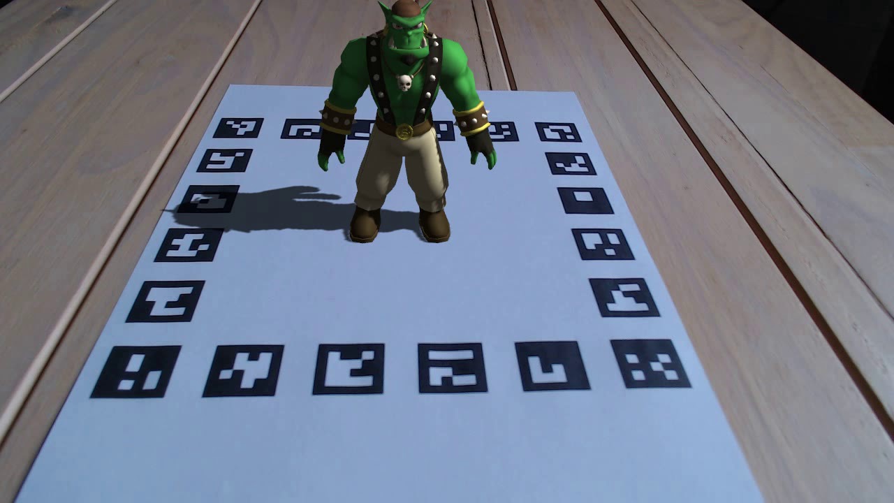
but could not remember who. The whole paper referred to it as merely a "virtual character": the audacityyyy. There was another figure in the paper that gave a better look of the character:

It's definitely an ogre - I know when I see one - and then I remembered. This is Sinbad, OGRE's official mascot as of January 2010. The character design and 3D model were made by Zi Ye with input from the OGRE community. Sergio Garrido Jurado et al were free to use the model in their paper but given the licence Sinbad was under, they were supposed to give appropriate credit and indicate the change that was made; as seen in the figure, Sinbad is moving around a "virtual floor" which idk is copied from where.
We shall do a better job at citation.
The chess scene you saw in this page is an artwork by Matthew Colbourne using the following assets from Polyhaven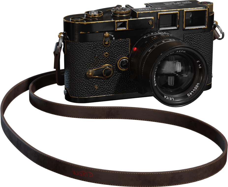 camera model
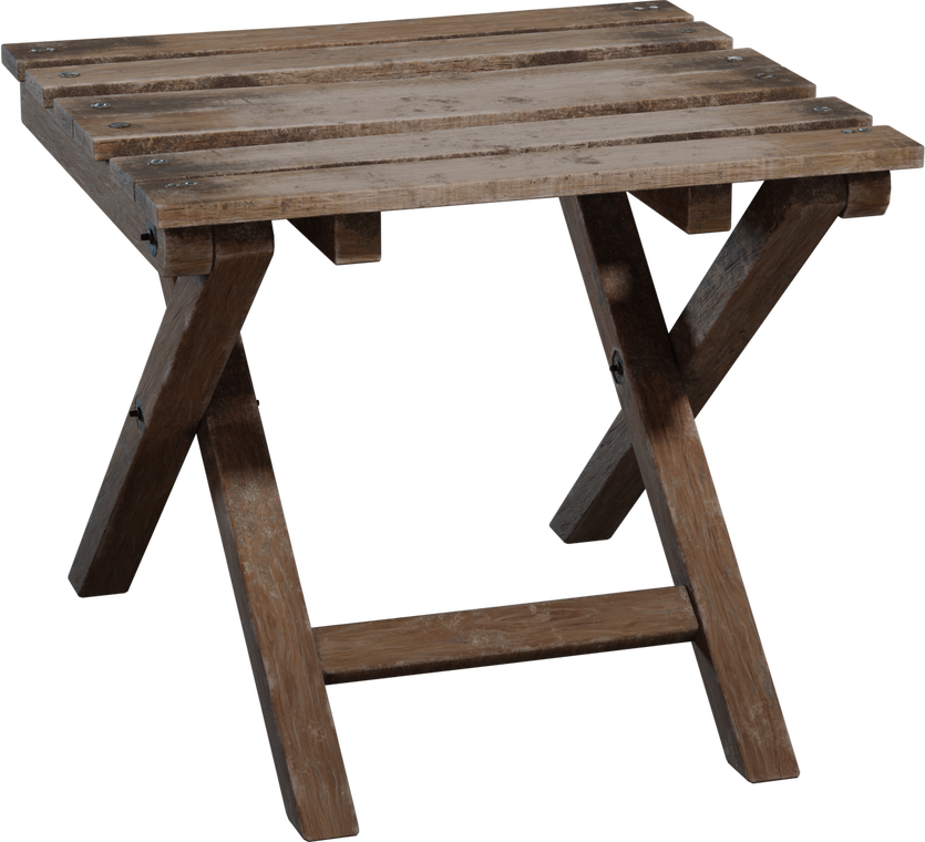 folding wooden stool model
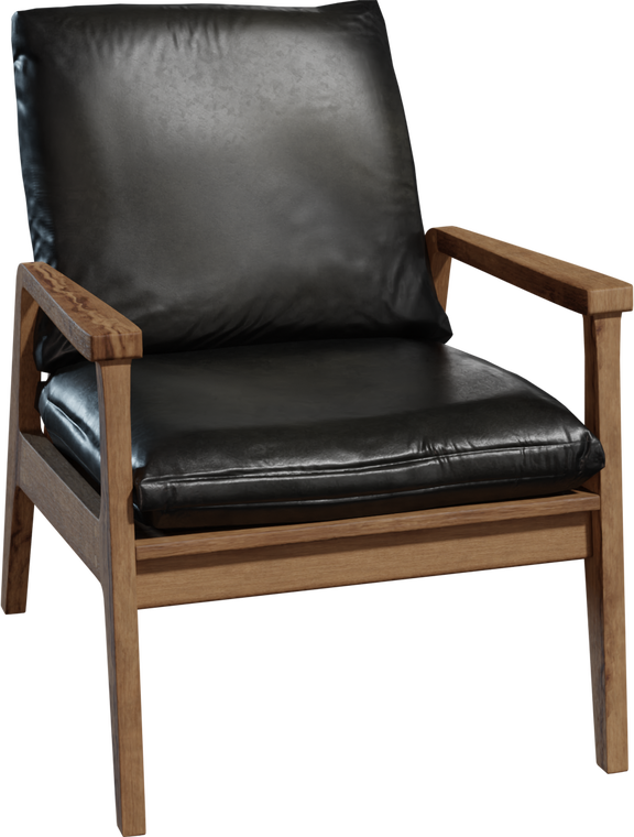 modern arm chair model
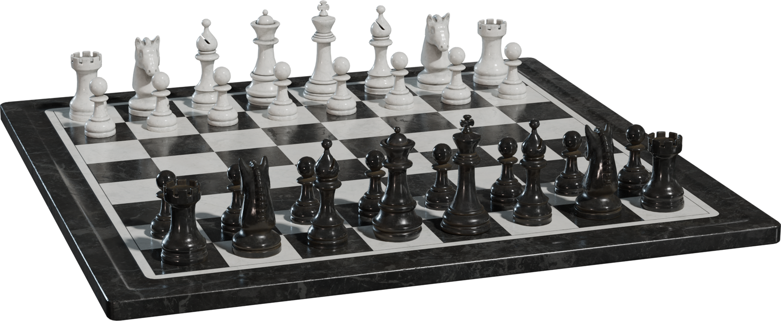 chess set model
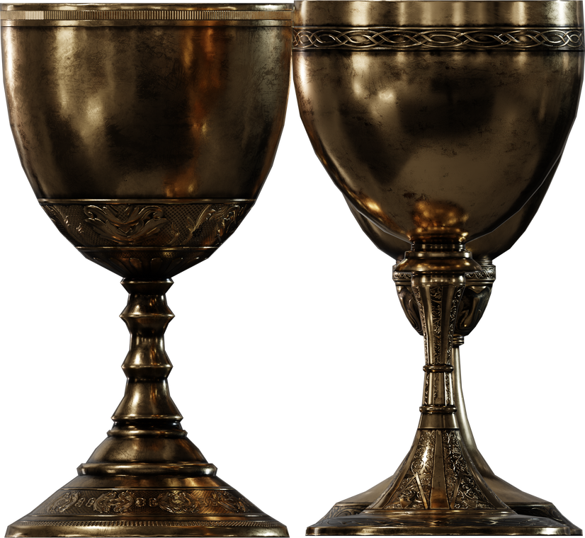 brass goblets model
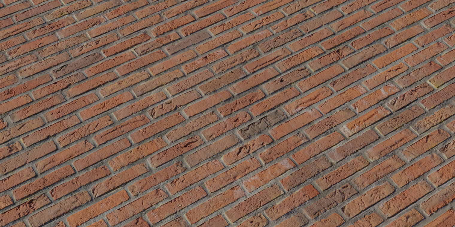 red brick texture
The simulator was developed by VACLAB. The camera pose estimation was done by Arnob - oh hi, that's me.
Although in the paper they applied their fiducial markers for camera pose estimation, the OpenCV implementation of ArUco does not track the camera but tracks the fiducial object. Tracking an object using a camera means continuously identifying its location when either the object or the camera are moving. 3D tracking aims at continuously recovering all six degrees of freedom that define the camera position and orientation relative to the scene, or, equivalently, the 3D displacement of an object relative to the camera. Now given the figures of the virtual scene the paper contains, some 3D tracking obvoiusly took place but we do not know which API they used, or in what format the API took the six degrees of freedom to give the virtual scene. Did they feed the pose of the camera to the API or did they feed the pose of the object to the API? Not sure if "API" is the proper term but I am using it in the sense that 3D tracking must be one program and projecting a virtual scene must be another so there may be an "API" connecting these two. Is the program that projects the virtual scene made by them from scratch? Well those are some of the questions we will never know the answers to, at least not through their paper. I guess there were people who realised this before me and so in the video where Jurado demonstrates ArUco there are comments - asking for the source code - that are not attended to.
By the way, when I say we will never know how they used their 6 DoFs to project their virtual scene, I do not mean we will never know how to do the same thing they did. There is this video where Kevin Wood overlays a 3D model Baby Yoda on a real scene. Before you jump to that video, I am letting you know that they don't give away the code in the video because they are selling their source code.

Can't always expect altruism in the capitalist world, can we? But sometimes, it's Christmas:
pip install opencv-contrib-python==4.8.1.78 numpy), they don’t bundle OGRE3D. That’s why ovis isn’t part of the wheels you can install from PyPI.
The ovis module has a class WindowScene which is the associated scene and a 3D viewport caused by its virtual camera.
The ovis module works very well with the aruco module. OpenCV gives us the pose of the fiducial object with respect to the camera, not the camera pose with respect to the object.
But to the setCameraPose() method of WindowScene, if we pass the pose from the aruco module and set the boolean argument invert=True, ovis does the calculations behind its veil and finds the camera pose.
If we then want to know the pose of the camera, the class includes a method getCameraPose().
Maybe in a lot of projects around but not in our one. As a programmer, ovis would be convenient for this project but would also burden it with a heavy dependency. The project currently does not demand a 3D rendering, at least not a rendering that demands a Ogre window, so given the state of this project ovis has been avoided.
Sure, if you want to put it that way, let's take a look at their tutorial. According to ChArUco Pose Estimation official tutorial by OpenCV, the coordinate system of the CharucoBoard is placed in the board plane with the Z axis pointing out, and centered in the bottom left corner of the board. According to the MATLAB reference for generateCharucoBoard function, the top-left corner value represents the origin of the board. Maybe MATLAB's implementation of ChArUco is different from that of OpenCV, right? Yes and no, let's clarify this.
ChArUco came to MATLAB only in 2024. By 2024 OpenCV saw a lot of changes in its ChArUco but the "bottom left" remained like a zombie in all the versions, written till date (2025-08-31), of the tutorial. Let us spot the grave of this "bottom left" to give peace to its soul.
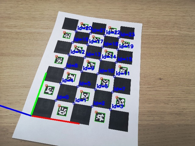 Charuco Board Axis. OpenCV version 4.5.5
 Charuco Board Axis. OpenCV version 4.6.0
Both images are of the same ChArUco board in the same orientation. For 4.5.5 image we can see that indeed the coordinate system of the CharucoBoard is placed in the board plane with the Z axis pointing out, and centered in the bottom left corner of the board. But in 4.6.0 the coordinate system of the CharucoBoard is placed in the board plane:
The man behind this change is Alexander Panov who fixed the object points order in ChArUco board.